
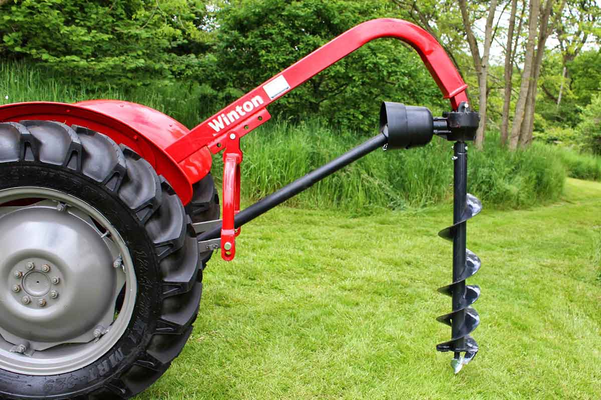
The Winton Post Hole Borer is a handy bit of kit which allows you to drill post holes for strong and sturdy fences. For greatest ease of use, it is vital that the machine is well-maintained. Only work on your machine when the tractor and machine are stationary and the keys are out of the ignition.
Attaching the Machine
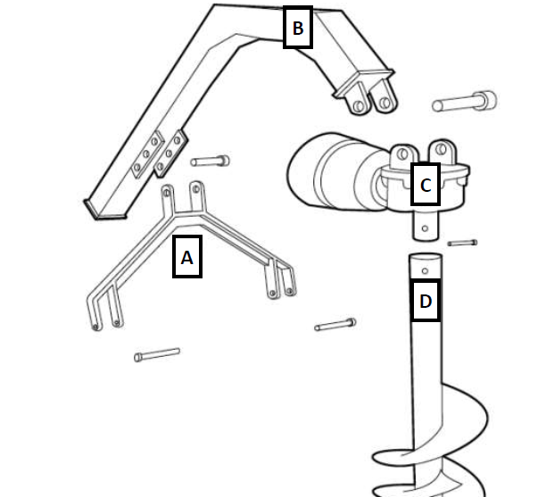
- Connect the lower link points on the machine’s A frame (A) to the tractor’s lower linkage arms.
- Attach the main support arm (B) to the tractor’s top link area using the top link pin. The top point of the hole borer should fix directly to the top linkage point on the tractor. If you have a top linkage arm fitted you will need to remove this to access the mounting point.
- Then connect the A frame (A) to the outer pivot hole (pivot hole furthest from the tractor) under the main boom (B).
- Raise and lower the tractor’s linkage to check the range of movement. Moving the pivot pin closer to the tractor will increase the height the arm (B) will lift.
- Then attach the gear box (C) (input PTO shaft facing the tractor) to the arm (B) by aligning the holes and inserting the mounting pin.
- Check the length of the PTO drive shaft by separating the telescopic shaft and attaching one section to the tractor PTO and the other to the digger gear box. Hold both sections together and parallel. Lower the main arm so the gearbox input shaft is aligned to the PTO shaft. Ensure the PTO shaft has a clearance of at least 150mm. Repeat the process at the maximum lift height of the boom. The minimum overlap must be 300mm when working and the driveline must be able to travel at least 30mm.This operation will determine the correct operating length of the drive shaft. The shaft may need to be cut to size.
- Connect the PTO drive shaft to the gear box (C) and other end to the tractor PTO. Check that it correctly meshes at both ends. Always couple the two ends of the driveline and check they are locked in place. Completely insert the sprung lock pins into the grooves in the PTO shaft on both the tractor and machine sides. If a shear bolt or slip clutch safety system is used on the PTO shaft this should be mounted on the implement end.
- Connect the auger (D) to the output shaft of the gear box (C) with the shear pins. Tighten the nuts securely.
- Raise and lower the linkage carefully to ensure sufficient ground clearance can be maintained. Adjust the tractor’s ‘sway chains’ or linkage adjusters to prevent any side-ways movement.
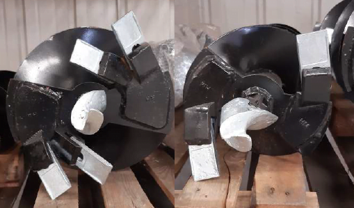
Auger Blade and Tip Replacement
You may wish to remove the auger from the machine to change blades. Do this by removing the pin securing the auger. If the auger is to remain attached, then sufficiently lift the machine so that the blades can be accessed easily. Always support the machine on rigid supports and ensure it is stable before carrying out any work. The blades must always be replaced if they are damaged, bent, worn or blunt:
- The blade teeth are held in using the rubber tube, pull the blade out from the unit to release this.
- Insert the new blade and rubber tube.
- The auger tip can be removed by unscrewing the securing nut and bolt.
- Replace the blade and then replace the nut and screw.
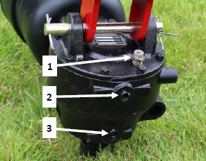
Oil Check and Change
Do not mix old and new oils together or mix different types of oil. Always dispose of old oils safely and in the correct manner. Always make sure the gearbox flat and level when checking oil levels. The machine should be left at a standstill to cool down for at least 10 minutes. Ensure the machine is stable before carrying out work and will not upturn.
- Remove breather/filler plug (1) and level plug (2).
- If draining and replacing oil remove drain plug (3) and let the oil drain out. Replace drain plug (3).
- The oil level should be up to the edge of level plug (2).
- Top up with oil (if required) using filler hole (1).
- Replace both filler/breather plug (1) and level plug (2).